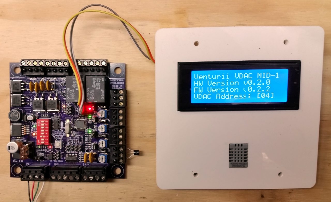
Venturii VDAC MID-1 Rev 2.0 PCB showing version info on LCD Display
Today’s news in bullet form:
- Soldered a second Rev 1.0 board, first “official” test of the multi-drop protocol.
- While troubleshooting an intermittent communication issue, discovered that the RS-485 transceiver I ordered for the MID-1 project is a 3.3V model, not a 5V. Replaced with an equivalent 5V variant – no difference in comm issue.
- Studied other designs and reference material, installed a 10k pull-down resistor between A and ground – scope edges became square where they had been ski hills before. Comm issue went away.
- Two days after soldering up my second Rev 1.0 prototype, the Rev 2.0 prototype PCB’s arrived in the mail. !!! Yay!
- Testing on the first multi-device comm bus has yielded a new, interesting problem.
The second revision of the VDAC MID-1 board has been assembled and so far it looks like this revision has indeed fixed all of the design flaws and “bugs” of the Rev 1.0 board. That was very encouraging to see so many things work right from the get-go, and this version also includes numerous new features as well. With three fully-assembled MID-1 VDAC’s, I have been finally able to do some proper testing of the multi-drop protocol. The results of those tests have been mixed. Some aspects of it have worked as expected, and I’ve encountered two new problems – one which appears to be in hardware and one which appears to be in software. Since I love to write, teach, and to tell stories, perhaps this new problem can best be explained in a story of sorts. Here goes.
Suppose there are two people trying to have a conversation with each other. Let’s make these people both in the army: one is a commanding officer and the other is a soldier. The commanding officer barks questions at the soldier, and he replies to the commander’s order when spoken to. No trouble with the communication in this situation. This is the same as it is with a single device on the communication bus. The VDAC module software queries the VDAC device, and it replies. There is no other traffic on the bus, so either side can safely assume that anything that is said is coming from the other party.
Now let’s add two more officers into the room. The commander speaks to each officer with a list of instructions. He might say something like, “Soldier A: I have three things to say to you. Thing 1 … Thing 2 … Thing 3.” As long as the commanding officer is speaking to one of the other two soldiers, the remaining two need not necessarily pay attention to the commander. In fact, they could all be working at desks, filling out paperwork or some other orderly task. It is only when the commanding officer calls out “Solder x” that all three must pay attention to ensure that if the commander is talking to them, that they pay attention, focus on what he is saying and then respond appropriately.
Now we enter into the area where my present dilemma exists. During the conversation between the commander and Solder A, the commander (or even the soldier) may actually say something that sounds like the commander addressing one of the other soldiers. This causes that soldier to perk up and start listening, but since it is a “false alarm” and neither of the other two were actually talking to him, he neither does his regular work anymore (because he is trying to find out how many things the commander has to say to him, nor does he actually get what he is waiting for from the conversation in the room – further instructions. Now he is basically “out of sync” with the conversation, and when the commander actually does address him, he is confused and does not reply until the commander repeats the question.
Ok, so it’s a loose analogy, and perhaps it does a better job of explaining my problem than of describing a likely real-world situation. However, it is, in effect what is happening. All three devices start to converse on the bus, but at seemingly random intervals, one of them will simply stop responding. The way the timeouts are set up at the moment, this causes everyone else to wait too in order to exaggerate the problem, and everyone has to essentially time out, clear their incoming packet buffers and the VDAC module has to re-send the last command before the addressed device responds properly. Originally I thought this might be the result of a problem with the hardware, since it seemed to work fine when there were fewer devices (1) on the bus. However inspection of the last packet “sent” to the devices reveals that there is in fact a segment of data sent on the wire that resembles the beginning of a packet addressed for one of the other devices on the bus. Appropriately, it begins to capture the data on the wire, waiting for the correct number of bytes to be received but this quantity is not satisfied. The conversation between the VDAC Module and the (other) device ceases, the VDAC Module now queries the perked up device, but this query too does not fill the required quotient of bytes, so it waits for more and does not respond, so both sides timeout and the module re-sends the query. Having purged it’s listening buffer now, the new message makes sense, is captured correctly and responded to appropriately. However, it is usually only a matter of seconds or minutes before another mischievious packet triggers this mysterious timeout problem again.
Some of the techniques I’ve seen used in other similar protocols include things like having a single, unique start-of-packet byte that no other message could possibly include. I’m not entirely sure that’s possible with this protocol since I want to be able to use the full range of 8-bit characters in the data payload, and there are no characters that are “off limits” to the onboard device types, and indeed some of them make use of all the characters.
One other technique I have seen amounts to using fixed-length messages, which I’d like to avoid if at all possible. The very nature of the VDAC protocol is such that it is very efficient, but needs to be flexible to ensure that efficiency.
Another technique I’ve encountered includes a multi-byte SOP sequence. This might make more sense for my case, although it is still not impossible for a multi-byte SOP to be encountered within the body of a message’s payload.
The solution that might make the most sense is to re-arrange the byte order a tiny bit, moving the checksum byte from the end of the packet to a fixed location closer to the beginning of the packet. Nope, nevermind – that won’t work either. We can’t effectively compute the checksum byte until the entire packet has been received, and if the packet length byte is [wrong], we’re right back where we started: potentially waiting for data that isn’t coming. Perhaps a variant of this could be used though, computing a checksum of the packet “envelope” bytes: the SOP, address byte, and length byte. If we added a header checksum byte after this sequence, any listening devices could detect early on that something is amiss with the header and discard it early. It would still be mathematically possible for the correct sequence of bytes to be encountered by accident in the wild, but the probability of this would now be exponentially lower. At some point I want to enable devices that share the same comm bus to “listen” to updates from other devices on that bus and use their data as inputs for local operations. For example, it would be possible to set up an analog output on one device to “follow” an anlog input on a different VDAC device by listening to the comm bus traffic and parsing out the bits that are of interest to it. This would require no server or host intervention, apart from querying the bus. Perhaps there could even be an “offline mode” where devices hold an election and choose one device to query the bus in the absence of a VDAC Module.
Anyway, this project is making good progress now, and most of the work to be done now is in the software. There are a few things I’d like to add, fix, or improve but they can all be done in code. This board has come together rather nicely.
