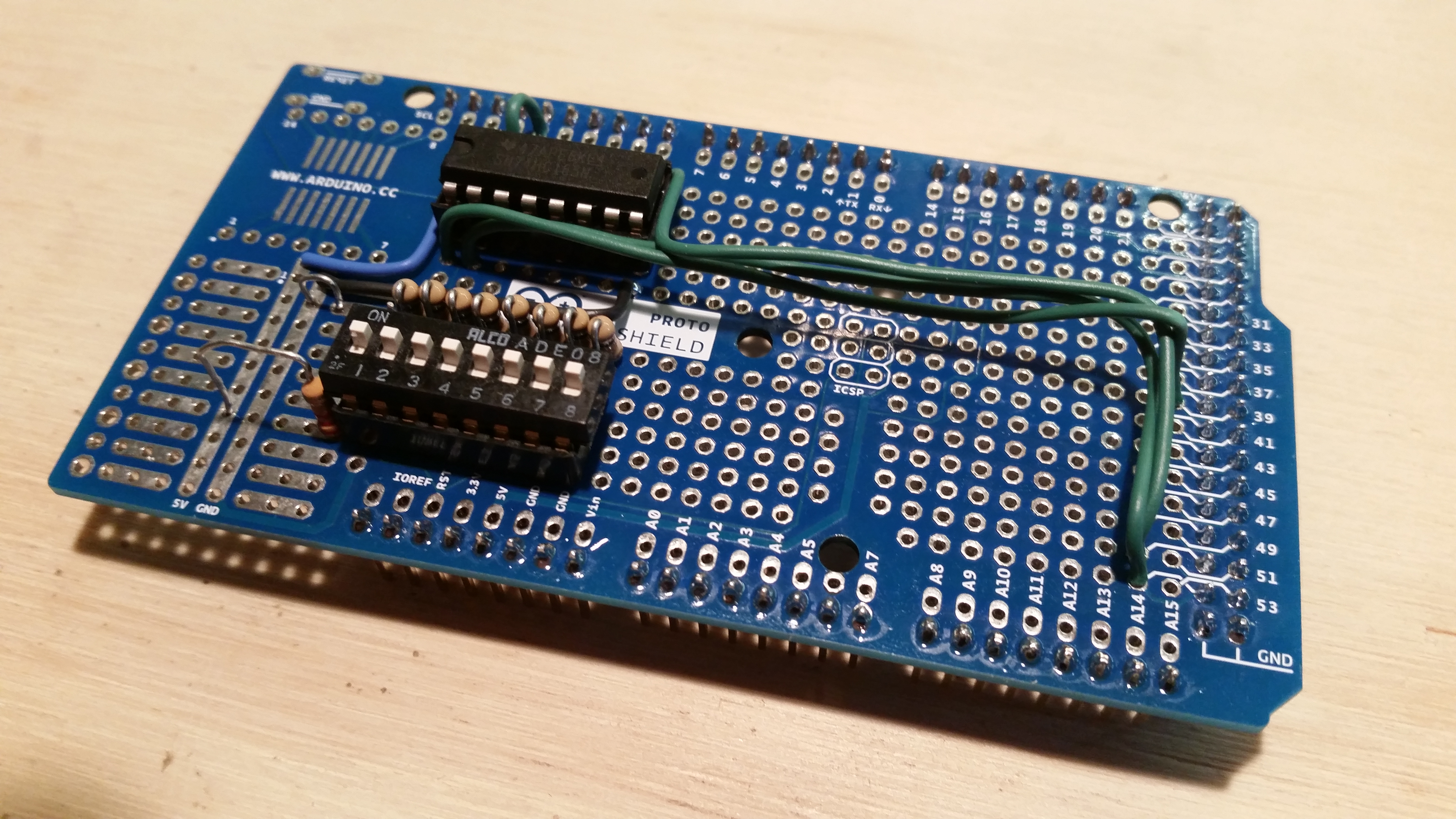
Using an Arduino Mega Proto-Shield, I am starting to prototype the various circuits that will form the NIM-1.
The push is on to get the NIM-1 prototype built. In order to help facilitate this, along with the necessary firmware development, I’ve begun building mini-prototypes of the various circuits that will form the Venturii VDAC-NIM-1 system. In this case, the first test circuit was of the DIP switch block and shift register for determining the base operating parameters of the NIM. By using the same pins that the actual circuit calls for, I should be able to test out each circuit independently while simultaneously building the firmware that will form the foundation of the NIM. Once all the circuits have been proven, the lessons learned and any changes required will be merged into the PCB design and a prototype of the entire system made, soldered, programmed and tested.
Already I should point out that I’ve found and fixed four significant oops‘s that would have been show stoppers! I cannot understate the importance of checking every detail in data sheets when designing a Printed Circuit Board! Electrical specifications & characteristics, mechanical specifications, clearances, spacing, part & pad size, heat dissipation, proximity derating, and the list goes on and on. It can certainly be a daunting task! However, close attention to detail at the design stage can save hundreds of dollars of repairs and re-runs down the road, not to mention time lost and materials wasted.