Tales along the way in my quest to Integrate Everything.

Years ago I used to work for the local cable company doing residential installations. During those travels, I got to see the insides and outsides of many homes covering the full spectrum of domaciles, and nothing seemed quite as inviting as an illuminated doorbell button. “Look at me, I am all lit up – press here to be welcomed inside!” it would say. However, as with all light bulbs, especially incandescent ones, the light inside would eventually burn out and it’s warm inviting glow would shine no more. When we bought our house, it’s doorbell buttons, front and back, had lights within that were already burnt out, and so the buttons worked but were not nearly so inviting. I went to the local home depot and bought new ones to replace them, but they were more costly than I would have liked, and I knew they would burn out again long before I felt I’d gotten my value from them. Surely there had to be a better way.

doorbell_button_original

Anyone who knows me or has been around me long enough has probably heard me express my distaste of LED lights. What should be clarified is that it is not LED’s themselves that I am opposed to, but rather using them incorrectly. What I mean is that LED’s are great for indicators, status lights, pilot lights, etc. They are NOT great for general lighting. However this, being a situation requiring indication and not general lighting, would be a perfect application for a retrofit to LED lights.


doorbell_button_guts

I started by removing the button from the door frame and inspecting the contents; there really was not much to it. The button is set up in such a way that power from the transformer flows through the light bulb and through the coil of the doorbell coil where there is enough resistance to prevent the coil from activating. However, when you push the button, this effectively shorts out the light bulb, causing enough current to flow to the electromagnet inside the doorbell, pulling in the plunger and striking the metal bell (or bar.) Ding Dong.

I removed the small incandescent light bulb from the circuit board and mounted a single green LED with an appropriate resistor in it’s place. It is at this point that I should back up to point out that my doorbell buttons do not actually run to my doorbell. Several years ago I re-wired them to run back to an input on a board controlled by Venturii so that I could interrupt any doorbell button presses and have them do other things besides just ringing a bell. I also put them on a schedule so that after hours when the kids are in bed & asleep, the doorbell will not ring but instead a visual indicator is activated. This setup worked fine when the light in the doorbell button was burnt out, but now that I wanted to light them up again I had to alter my plan. With an incandescent bulb in the switch, I installed a 24V relay at the other end, and the 16 VAC from the doorbell transformer was enough power to throw the relay when the button was pressed. With a single LED in there instead of the incandescent lamp, the relay FLIPPED OUT! It sounded like one of those old fashioned, mechanical buzzers.

doorbell_button_single_led

This made sense, since on every half cycle the diode (LED) would conduct current, causing the relay coil to activate for half the cycle and rest the other half when the LED blocked the current. What I needed was two LED’s connected in parallel but each with different polarity so that on the positive half cycle one would light and on the negative half cycle the other would light, and there would be just enough current to keep the relay coil in place. That is exactly what I did:


doorbell_button_dual_led


I wrapped some tape around the wires on the inside since it was possible they would hit the metal bars that formed the switch, and re-assembled the unit as a whole. The LED’s and resistor all fit perfectly inside the case of the switch – it was like it was designed to accommodate LED’s OR Incandescent Bulbs.


doorbell_button_dualie_installation

Of course, I grabbed LED’s from my misc part bin, and as it turned out – the two Green LED’s I grabbed were slightly different colors! I also retrofitted the back doorbell switch with red LED’s and it looks slick – you can see it from a block away! My camera’s perception of “white” was a bit off in the picture, but you can see the effect the different green LED’s had. I was thinking what I might do if I retrofit another button would be to put in some self-controlled multi-colored LED’s instead to really make the button stand out. Two of those little guys would create quite the psychadelic button!

Doorbell Switch with Green LED's


… And just for completeness, the red model:


Doorbell PCB with Red LED's


Doorbell Button with RED LED's


Inner Workings of a Toilet Tank

Have you ever wondered how many times you (or your family members) flush the toilet in a day? Here is a simple way to find out.

Ironically enough, I got the idea for this project while sitting on the toilet. True, many an inspirational moment has transpired in like manner, but this one was particularly fitting. We have three toilets and 6 people in our house. Simple math says that’s two people per toilet. All of our toilets are the newer style six-litre-per-flush/clogs-every-other-time-you-use-it style, but the clogging issue is material for a whole other writeup / rant. A quick look inside the tank of one of these reveals two facts immediately:

  1. I have very clean water. Compared with many other toilet tanks I’ve taken the time to peer into, these are by far the cleanest ones I’ve ever seen. At aproximately 6 years old, there is no sign of scale or debris of any kind on the inside of the tank.
  2. There is more than 6 litres of water in there!

I pondered the question of just how many times per day each toilet was flushed. A recently failed ultrasonic humidifier left me with a cool little float switch, originally used to shut off the transducer if the water level in the resevoir dropped below a certain level, and I wondered if I might be able to mount such a switch inside the tank somehow to tell Venturii whenever the water level dropped, indicating a flush. But then, a simpler idea struck: Why not use a simple magnetic reed switch? I could mount the switch on the inside of the tank, and affix a magnet to the float ball close enough to the sensor that whenever the water level dropped, the magnet would fall with the ball float and return to rest once the tank was full. It was so simple it just might work.

Toilet Tank Float Sensor Calibration

I started by Dap’ing a magnet onto the float ball. The top of it was dry and I figured it would probably never actually go under water since in theory, that’s what a ball float does – it floats. Next was some testing to determine the best placement of both objects so that the sensor would give an accurate read of when the ball was up and when it had dropped. Putting my Digital Multimeter into the beeper mode of continuity testing helped in this process a lot as the meter would beep whenever the magnet was close enough to the switch to activate it. After some fanagaling, I secured both in place where they seemed to detect reliably.

Toilet Tank Float Sensor

Routing the wires out a convenient indent in the porcelain tank body allowed the lid to sit properly without causing any risk to the wires. I ran CAT5 cable to each toilet in the house in case future endeavors required PoE or Ethernet connectivity, and just used one of the pairs to connect the output of this switch to a digital input on my VDAC prototype board. Voila – Toilet Tank Status Monitoring in Venturii.

Wiring For Toilet Tank Float Sensor

Last but not least, in order to appease the ever-important Aesthetics Committee, the CAT 5 cabling was routed down the water pipe supplying the tank with it’s water. A couple of tie-wraps held it in place, and even on this toilet whose supply line came out of the floor a considerable horizontal distance from the tank inlet, the wire is barely visible.


Today's Upstairs Toilet Flushes

Our upstairs toilet was flushed seven times today.


Monitoring My Favorite Kitchen Appliance

Insinkerator Under The Sink

Instant gratification is rarely a good thing. The virtue of patience is not learned in an instant, but after repeatedly enduring opportunities to be patient while maintaining both one’s temper in the face of trying circumstances and a healthy perspective. Patience can work together with anticipation, and over time they spice up the reward long desired. Not quite the paragraph you expected to read beneath the header, above, is it? Let me esplain… No there is too much.  Let me sum up:

When I got married to my wonderful wife, I found all sorts of new things in the sink: Orange peels, potato peels, onion peels, banana peels, all manner of fruit and vegetable stems, husks, shells and skins. I quickly found that when I did not know what to do, I should clean something, and so it became my task to clean the kitchen after most supper meals. I would spend considerable time manually grinding up these things into bits and pieces small enough to squeeze through the straining bars at the bottom of the sink. In fact, I would often grind in a circular motion, pretending myself to be a garburator.

All those nights spent grinding up the leftovers from dinner’s preparation had me longing to install a real garburator. I’d been to friends’ houses who had them and loved the simple cleanup they offered. Growing up in an Irish household, I cannot begin to imagine the truckloads of potatoes my dear mother must have peeled over the years. All those potato skins were bagged up, tossed out with the trash and sent to landfills. While biodegradable, they certainly added to the bulk of waste produced by our household. As well, it is the organics in the trash that cause the most stink. Some day, I thought to myself, I will get a garburator!

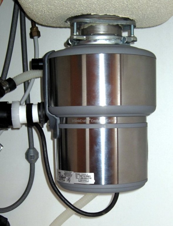
After at least a year or yearning, an opportunity presented itself to purchase one – in fact, quite a high quality “In-Sinkerator” brand food waste disposer. Although I had never done so in the past, I managed to install the unit in under three hours, and it was only a two-trip installation. (A lot of times I rate my installations in terms of trips – that is, how many trips I have to make to Home Depot before I had all the correct parts, tools and accessories.) The model we got had a full 1 HP motor and various design features to make it extra quiet while pulverizing whatever you placed down it’s throat. From that very first test until this very night, I have continued to challenge the unit with materials that I would never consider stuffing down a 3″ drain pipe. Invariably, it has reduced them all to crumb-sized bits and washed them down the drain with ease! All manner of peels and rinds, avocado pits don’t even make a bump. Un-popped popcorn, masses of potato peels, whole chicken and turkey carcasses go through bone like butter, all without the mess or stench of a pig farm. Without a doubt, it is my favourite kitchen appliance.

Electrically, it’s grinding force draws a lot of power, and one afternoon I was contemplating how I might be better able to ascertain how I spend money on electricity. I already monitor the current drawn through both electrical phases entering the house, and short of adding current sensors on every branch circuit I thought there might be better ways of figuring out what some of the peaks in the amperage graphs originate from. I started designing in my head a device that could be embedded into the electrical system of any household appliance, big or small, that would monitor even multiple devices within that appliance and report on their usage patterns. Take a refrigerator for example: We all know that refrigerators have a compressor, fans and light bulbs that turn on when you open the door. But most people would be surprised to learn that they also have electric heaters in them! Yes – the appliance that keeps your milk cold and your steaks frozen does so with the help of electric heaters! If I had a device that I could tie into the electrical system of the refrigerator to monitor when each of these components was used, I’d get a very interesting graph of how the appliance works; perhaps even some ideas on how to save electricity.

One of the first challenges with this idea is that micro-controllers run on 5 volts DC or less, while the fans, motors and heaters in the fridge run on 120 volts AC: nary the two should meet! Traditionally, to monitor AC power presence with a micro-controller, one could install a 120V relay and then connect an input pin through one of the Normally Open sets of contacts. When mains voltage was applied to the coil of the relay it would pull the contacts closed, make the Normally Open circuit and signal the micro-controller. While this does ensure electrical separation between the mains power and the micro-controller circuitry, this method has some drawbacks: 1. Cost. A typical 120VAC relay could run between $10 and $50, usually depending on the type of load switched. Since we are really only switching a signalling load, the smallest relay we can find would suffice. There is also noise: relays make a click when they activate and de-activate, and if the appliance turns components on and off frequently, the clicking noise produced by the relay may not pass the acoustic department of the aesthetics committee.


MID400 AC Presence Sensor Prototype

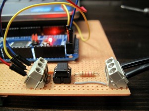
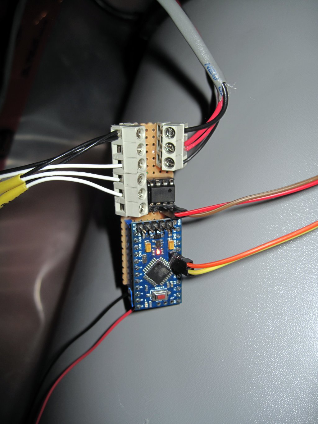
I started doing some research on ways to detect AC presence. There was a number of technologies that looked interesting, however I came across one component designed specifically for the task: The MID400. Basically comprised of a pair of LED’s aimed at a photo-sensor connected to a “slow” op-amp, the MID400 does exactly what I need it to. Connect the LED pair to the mains voltage with a suitable resistor for current limitation and each LED shines on the photo-sensor during it’s corresponding cycle of the alternating current waveform. The “slow” op-amp allows the output to remain low even during the zero-crossing when both LED’s would be off, but removal of power causes the op-amp to send the output high after about 50 ms if I remember correctly. See the picture above for my prototype; that is 120V AC connected to the terminal block at the right, and the three pins on the left are connected to my Arduino Mega, seen in the background. It was a suspenseful moment as I first connected the mains power to this small circuit. Let me just say that I checked the pins of the MID400 four or five times first! However, there was no smoke or loud bangs – in fact, the whole thing worked exactly as it was supposed to. There is no noise, these parts are cheaper than AC-driven relays, and small! The ones I bought to sample are an 8-pin DIP configuration. Later on, I added an [external] LED for visual confirmation when AC is sensed, and set one of these up to monitor when the In-Sinkerator is running. The output is sent back to a VDAC (Venturii Data Acquisition and Control) board, and monitored by Venturii.

It’s been running for several months now, and I’m hoping to get a test run of manufactured circuit boards made by Metal Minds in the next few weeks to replace my hack-job prototype. If the next prototype works well, we may begin to sell these as an AC presence sensor that could be used to detect whenever any AC appliance or device is on or off with any TTL-compatible input. The board takes 5VDC in, and the output pin goes high (+5V) whenever AC is absent (off) and low (GND) whenever the AC is detected (on.) The LED also reflects the AC presence, so long as there is 5v power to the board. Somewhere I have a picture of the revised prototype that is currently under my sink. The InSinkerator plug beneath the kitchen sink has two receptacles, so I have the InSinkerator plugged into one and my AC Presence Sensor plugged into the other; whenever the InSinkerator switch is turned on, it also sends power to to the AC Presence Sensor, which signals a VDAC board and this gets logged within Venturii. Optionally, I could have Venturii do something else when this input changes state – I just don’t know what would be useful.

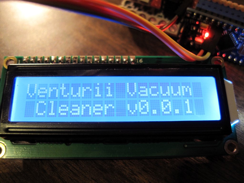
This proof of concept will hopefully pave the way for a new board I am working on in my head, to embed some more monitoring and/or manual, semi-automatic, or fully automatic control of the inner workings of other appliances. One in particular that comes to mind is the fridge, and I believe I have touched on this idea in another post – possibly on the Venturii Vacuum Cleaner. By incorporating a temperature sensor into the refrigeration and freezer compartments, and replacing the inner workings (usually mechanical timers, etc.) with a smart control board, it may be possible to reduce energy costs based on both internal intelligence (better motor, heater, and fan control directly related to temperatures of various components; even ambient air temperature) as well as external influences such as whether or not anyone is in the house, what time of day it is, what day of week it is, and how likely it is that someone is going to open either part at that time. It seems, based on my power consumption graphs, that the heater is governed not by any sort of sensor but by a mechanical timer that simply turns it on at a regular interval, whether or not the condenser coil is freezing up or not. This heater draws several amps – I’m pretty sure it’s as much as or more than the compressor motor and fans combined! If it didn’t need to run as much, electrical consumption would be reduced. Imagine also, the fridge ramping up the compressor runtime around breakfast, lunch, and dinner in anticipation of the door being opened more frequently, better compensating for heat gained every time it is opened.

There are so many ways appliances could be improved, by adding a little smarts to the way they operate. Of course, the flip side is that introducing new technology to replace a proven, albeit sub-optimal, control system adds a greater risk of malfunction. Suppose the new controller did not turn the compressor on when it should and all the food within the fridge warmed to room temperature before anyone noticed. What I need is a bar fridge or an old full sized fridge to tinker with as I develop and perfect these innovative technologies. Does anyone have an old fridge they’d like to part with for a good cause?

A Kenmore Built-in Vacuum Cleaner modified to add intelligence through Venturii integration

The Venturii Vacuum Cleaner

Several months ago, my wife phoned me during the day saying that the (built-in) vacuum cleaner would not shut off. Even with the hose unplugged from the wall, the motor in the basement continued to run. It was the Friday before a long weekend, and my wife loves a Several months ago, my wife phoned me during the day saying that the (built-in) vacuum cleaner would not shut off. Even with the hose unplugged from the wall, the motor in the basement continued to run. It was the Friday before a long weekend, and my wife loves a clean house. When I got home I inspected the unit and found the motor relay showed signs of temperature-induced housing failure, likely the result of significant heating of the contacts. A little Googling revealed that this was a common problem for this make and model of vacuum cleaner, and a new control board would cost about $130. Relay on DigiKey: $3.60. Opportunity to work on a wife-endorsed project ALL LONG WEEKEND: Priceless.

First of all I needed a hefty relay. The one that failed was a 30 Amp 24VDC relay. I found one similar to this in my relay bin, a 30 AMP, 24VDC coil N/O bigg’un. Now I could have simply soldered some lead wires over to the control board, the rest of which was perfectly healthy, and been done with it, but I wanted to work a little bit more magic into an otherwise mundane appliance. Enter Arduino.

I’d built several projects on the Mega series of Arduino boards, but a full Mega seemed like swatting a fly with a bulldozer in this case, and I had both a Nano and a Pro Mini laying around. Truth being told, I spent more time struggling with the Nano only to find out that there was something wrong with the board. (My Nano = DX Chinese Knockoff.) It would not program, either through USB or ISP, but I had never worked with a Nano before (or any 328 for that matter) so I wasn’t 100% sure I was *doing it right.* Eventually I gave up and moved over to the Pro Mini, which – after troubleshooting an issue with the 5v pins not being internally connected to each other while I assumed they were, it programmed right up. With a working microcontroller up and running, the rest was pretty straight forward. I added a little 2×16 LCD screen I’d bought on DX because it was too good a deal to pass up. I put together a little breadboard and soldered some jumpers. The relay control itself was a first for me, being that it was a 24v DC powered coil. Spec sheet said it needed something like 65mA holding current but inrush could be over 110mA. As well, I had not worked with 24v before, switched with silicon; I suspected that smoke could be in my near future.

I started looking at other circuit boards with relays and checking out the drivers they used to switch the power to their relays. The one I ended up utilizing was a 2 channel high current driver that I pulled from a broken access control board (a first generation Mercury MR-12 or Lenel LNL-1320 to be specific.) According to the spec sheet, it was more than capable of handling the required current to run this relay. This should solve the problem of motor control. Now what should I have the LCD screen say? Originally I had a very practical screen that simply stated that the motor was idle when in fact it was, and then claimed the motor was running as the case may be. However, this information would certainly not be new to anyone standing close enough to the unit to read the words on a tiny LCD screen. By creating different inputs for each vacuum “hole” in the house, and separating the wires that originated at each, I could now have it display *which* hole was calling for vacuum, and therefore *where* the dust it was collecting was coming from. Finally, because I love to integrate things, I embedded some code from my existing Venturii platform so that it could report the status of all the inptus, allow remote control of the motor and also allow remote control of the LCD screen through Venturii. The Venturii Vacuum Cleaner was born.

Once this was all set up, I decided to put witty sayings on the LCD screen when the motor was idle. This was harder than it sounds since you have to try to come up with things a vacuum cleaner might say like “I Love Dust Bunnies” or “Being A Vacuum Cleaner Sucks.” Every day my older two girls would check the vacuum cleaner, and then ask me when I got home why I hadn’t updated it yet. They got quite a kick out of it, but unfortunately my creativity dried up after about 4 or 5 vacuum cleaner sayings. None the less, it still works and best of all – my wife is happy I keep the floor so clean. clean house. When I got home I inspected the unit and found the motor relay showed signs of temperature-induced housing failure, likely the result of significant heating of the contacts. A little Googling revealed that this was a common problem for this make and model of vacuum cleaner, and a new control board would cost about $130. Relay on DigiKey: $3.60. Opportunity to work on a wife-endorsed project ALL LONG WEEKEND: Priceless.

First of all I needed a hefty relay. The one that failed was a 30 Amp 24VDC relay. I found one similar to this in my relay bin, a 30 AMP, 24VDC coil N/O bigg’un. Now I could have simply soldered some lead wires over to the control board, the rest of which was perfectly healthy, and been done with it, but I wanted to work a little bit more magic into an otherwise mundane appliance. Enter Arduino.

I’d built several projects on the Mega series of Arduino boards, but a full Mega seemed like swatting a fly with a bulldozer in this case, and I had both a Nano and a Pro Mini laying around. Truth being told, I spent more time struggling with the Nano only to find out that there was something wrong with the board. (My Nano = DX Chinese Knockoff.) It would not program, either through USB or ISP, but I had never worked with a Nano before (or any 328 for that matter) so I wasn’t 100% sure I was *doing it right.* Eventually I gave up and moved over to the Pro Mini, which – after troubleshooting an issue with the 5v pins not being internally connected to each other while I assumed they were, it programmed right up. With a working microcontroller up and running, the rest was pretty straight forward. I added a little 2×16 LCD screen I’d bought on DX because it was too good a deal to pass up. I put together a little breadboard and soldered some jumpers. The relay control itself was a first for me, being that it was a 24v DC powered coil. Spec sheet said it needed something like 65mA holding current but inrush could be over 110mA. As well, I had not worked with 24v before, switched with silicon; I suspected that smoke could be in my near future.

I started looking at other circuit boards with relays and checking out the drivers they used to switch the power to their relays. The one I ended up utilizing was a 2 channel high current driver that I pulled from a broken access control board (a first generation Mercury MR-12 or Lenel LNL-1320 to be specific.) According to the spec sheet, it was more than capable of handling the required current to run this relay. This should solve the problem of motor control. Now what should I have the LCD screen say? Originally I had a very practical screen that simply stated that the motor was idle when in fact it was, and then claimed the motor was running as the case may be. However, this information would certainly not be new to anyone standing close enough to the unit to read the words on a tiny LCD screen. By creating different inputs for each vacuum “hole” in the house, and separating the wires that originated at each, I could now have it display *which* hole was calling for vacuum, and therefore *where* the dust it was collecting was coming from. Finally, because I love to integrate things, I embedded some code from my existing Venturii platform so that it could report the status of all the inptus, allow remote control of the motor and also allow remote control of the LCD screen through Venturii. The Venturii Vacuum Cleaner was born.

Venturii Vacuum Cleaner Microcontroller

Venturii Vacuum Cleaner Controller


A 2x16 LCD Display on the Venturii Vacuum Cleaner

The Venturii Vacuum Cleaner LCD Display

Once this was all set up, I decided to put witty sayings on the LCD screen when the motor was idle. This was harder than it sounds since you have to try to come up with things a vacuum cleaner might say like “I Love Dust Bunnies” or “Being A Vacuum Cleaner Sucks.” Every day my older two girls would check the vacuum cleaner, and then ask me when I got home why I hadn’t updated it yet. They got quite a kick out of it, but unfortunately my creativity dried up after about 4 or 5 vacuum cleaner sayings. None the less, it still works and best of all – my wife is happy I keep the floor so clean.